Summary
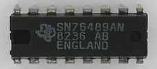
This page provides some detailed 'research' type information about the SN76489 sound chip, as used in, for example, the Acorn BBC computer. Since I have probably delved a little deeper than most, I thought I'd better share what I found. In particular, I have found the exact bit sequence output by the white noise generator.
While reading this information, please refer to the SN76489 data sheets, as available here.
The SN76489
The SN76489 is a simple sound chip that contains four independent 'square wave' sound generators (three tone generators and one noise generator), whose digital output signals are (programmably) attenuated, mixed on-chip, and output as an analog signal.

It is immediately important to note that the output of a sound generator can only be 0 or 1. At the chip output, however, i.e. in the analog domain, the signal actually varies between '-x' and '+x' volts. I.e. if tone generator 1 outputs a 100 Hz signal, and the other sound generators are silent, the output is -x volts for 5 ms, then +x volts for 5 ms, then -x volts for 5 ms, etc.. However, when measured, due to the additional circuitry connected to the chip output, the square wave usually becomes a sine wave at higher frequencies.
All four sound generators take a programmable clock signal (derived by division from the external clock) as their input, and output a bitstream (except for the periodic noise generator, see below). The tone generators simply output their clock (if based on the 'external clock / 32 / N' formula). I.e. if the external clock is 4 MHz and N is 25 (which equals the divisor value programmed into a sound generator register, called N in the datasheets), the result is a square wave of 5000 Hz. The noise generator can generate either white noise or periodic noise (depending on the setting of the 'FB' bit in the noise control register). The white noise generator outputs either a 0 or a 1 every clock, equal to the output of a pseudo-random generator. The periodic noise generator, finally, has a cycle of 15 clocks. It does *not* output for fourteen of them (i.e. it is basically tristate), and it outputs '0' for one.
The pseudo-random generator
Since no documentation I found on Internet provided details about the internals of the pseudo-random generator used to generate white noise (indeed, most of the information I did find complained about the total lack of documentation !), I set out to find the actual bit sequence generated by the pseudo-random generator. After all, pseudo-random generators repeat. And there is no real reason to know the circuitry used if the resulting bit sequence is known.
After some experimentation (looking for the most convenient frequencies, volumes, sample rates, etc.) I programmed the SN76489 in my Acorn BBC computer to generate a 5000 Hz signal with tone generator 3, and a white noise signal (of tone generator 3 frequency) with the noise generator. I then digitised the output signal on a PC with a Soundblaster at 48000 Hz (16-bit mono) and exported the raw data to my Acorn Risc PC, to be analyzed. The neat trick here is that the tone generator 3 signal and the noise generator signal are synchronous ('noise on top of square wave'), so the tone generator 3 signal serves as a continually recognizable clock signal. After building a suitable analysis program, the raw data was four-level thresholded, compressed in the time domain (based on the tone generator 3 clock detected in the signal), and the noise bits were determined by subtraction. Then the periodicity of the noise signal was tracked down. It was periodic (Eureka !). And it has a cycle length of 32767 (2^15-1), indicating quite clearly that the pseudo-random generator is a 15-bit shift register construction ! The datasheets mention zero-suppression circuitry, which explains the '-1'.
The bit sequence I thus managed to mangle out of the SN76489 is available here.
Generating the sequence on the fly
Several interested folk have suggested generator formulas, usually, it seems, after feeding the bit sequence to a brute force analyzer of some sort. I've found the following pseudo-code (with zero suppression built in) works elegantly :
- feed_bit = old_value[1] XOR old_value[0]
- new_value[14..0] = old_value[14..0] >> 1 OR feed_bit << 14
- output of the generator : the inverse of new_value[0]
In, e.g., ARM code, this is (rm = 1 << 14, rv = random value, rx = scratch register) :
EOR rx,rv,rv,LSR#1
AND rx,rm,rx,LSL#14
ORR rv,rx,rv,LSR#1
and, e.g.,
TST rv,#1 to determine the output bit (if EQ, 1, if NE, 0)
The start value of this generator (after further experiments) seems to be the bit sequence 100000000000000. I.e. this is the reset value of the white noise generator, e.g. as forced after writing to the SN76489 noise frequency register. My experimentally determined bit sequence, mentioned above, has a 'skew' of 20862, i.e. the bit matching the actual start of the sequence is the 20862nd bit.
Other useful information
A very good and detailed amount of SN76489 info can be found here.
Signing off
Feel free to use this information to enhance your own SN76489 emulation code, if you give me a suitable credit.
Research and this text by John Kortink.
First published 15 March 2002.